Introduction

|

|
Define a Problem
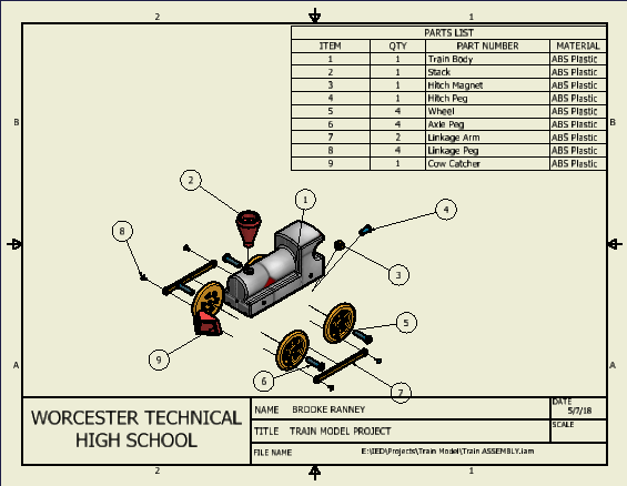
My train model consists of 9 parts, and a straight train track: the train body, stack, hitch magnet, hitch peg, axle peg, linkage peg, linkage arm, wheel, and cow catcher, that are all constrained to the proper parts and move in proper ways. In the end, my train could move by the rolling of its wheels across the track without any parts being moved in wrong directions (see extra credit video at the bottom of this page).
Generate Concepts
I started modeling my train by reading the dimensions of each part while sketching it out in inventor. The packet that we were given showed us most of the dimensions, but some we had to figure out for ourselves. Some of the parts were difficult to create, so I had to watch videos on how to use the inventor commands to make each part. The drawings below show each of the models and their correct dimensions.
Develop a Solution


Construct and Test Prototype
Degrees of freedom: (all parts)

|

|
Exploded Assembly View:
Evaluate the Solution
I showed my original train model to both of my parents when the colors were a lot different than my final product. My mom recommended that I changed the stack and the cow catcher color to red (I originally had it as blue), because she thought that I had too much blue which "clashed". My dad also made a recommendation that I should make the wheels a brighter color gold and make the linkage arm and hitch magnet a darker gold. They both liked the way that my train was styled and thought that it looked very "realistic." I showed my final train product to my friend Sadie and Josh, and they both agreed that it would move well if it was to roll on its wheels across the track. I then showed them the extra credit video that I made to prove their point.
Present the Solution
I really enjoyed making this project, because I learned even more about the uses and tools of inventor. I also really liked getting used to applying assembly constraints to complete the train, and I now feel like I'm and expert at it. The color picking of each train part brought on my creative side, and I think that I spent a little too much time deciding which colors would go well together; in the end I think it turned out really cute. I personally thought that the train body was the hardest to dimension, especially the arc on he back. If I created it wrong from the start, inventor would not let me extrude certain parts; eventually I had to redo it. The rest of the models, however, weren't that difficult to make, and were actually pretty interesting.
The purpose of a sectioned view is to improve your ability to visualize the complete object that is being drawn.
The purpose of an auxiliary view is to show the true shape and size of a sloped surface of an object.
The purpose of a broken view is to display the drawing view of an object in a larger scale on a smaller sized drawing sheet.
Symbols are used instead of words to identify hole types, because it is a lot quicker and easier to read and write little symbols than full words and sentences. Symbols can also be more precise and accurate, as words could be mistaken for a different meaning if not read right.
Machines can't create dimensions that are out of value range, so we must create degrees of variation. If a part is created but has dimensions that are out of range, and tolerances are not used, the part is not usable.
